


Standard grades for leakage volume of control valves and test methods
Addtime:2023-09-12 From: View:461
1. Standard for leakage volume of regulating valves:
National Standard GB/T4213 Leakage Level Test Test Medium Test Pressure Maximum Leakage Volume per Hour I User and Manufacturer Determine II Water, Air or Nitrogen A5×10-3×Rated Capacity of Valve III 10-3×Rated Capacity of Valve IV Water A or B 10-4×Rated Capacity of Valve Air or Nitrogen A IV-S1 Water A or B 5×10⁻⁴×Rated Capacity of Valve Air or Nitrogen A IV-S2 Air or Nitrogen A 2×10⁻⁴×ΔP×DV Water B 1.8×10⁻⁷×ΔP×DV Air or Nitrogen A 3×10⁻³×ΔP (Continued Table Leakage Volume)
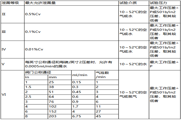
American Standard ANSIB16.104 Leakage Grade Maximum Allowable Leakage Volume Test Medium Test Pressure Grade II 0.5% Cv 10 - 52°C air or water Maximum working pressure difference △P or 501 lb/in2 pressure difference, take the lower one Grade III 0.1% Cv 10 - 52°C air or water Maximum working pressure difference △P or 501 lb/in2 pressure difference, take the lower one Grade IV 0.01% Cv 10 - 52°C air or water Maximum working pressure difference △P or 501 lb/in2 pressure difference, take the lower one Grade V per inch nominal diameter and per pound/in2 pressure difference, allow 0.0005 ml/min leakage at 10 - 52°C water Maximum working pressure difference △P Grade VI valve nominal diameter ml/min bubble number/min 10 - 52°C air or nitrogen Maximum working pressure difference △P or 501 lb/in2 pressure difference.
Leakage standard of control valves (National Standard GB/T4213)
The national standard GB/T4213 for regulating valves stipulates six levels for leakage. The specific regulations are shown in the table below. The lowest level is Level I, which has no specific requirements; the highest level is Level VI, which is the bubble level. When the leakage volume is greater than 0.5% of the KV value, testing is exempted.

II. Orifice Diameter Comparison Table for Regulator Leakage Quantities

Note: 1. The number of bubbles per minute was measured under the condition that a 6mm outer diameter and 1mm thick pipe was vertically immersed in water at a depth of 5 to 10mm. The surface of the pipe end should be smooth.
2. If the diameter of the valve seat differs by more than 2mm from one of the values listed in the table, the leakage coefficient can be obtained through the extrapolation method under the assumption that the leakage amount is proportional to the square of the valve seat diameter.
III. Leakage standard for American National Standard B16.104 control valves:
IV. Test Method for Leakage Volume of Control Valve
Type A testing method
1.1 The test medium is clean gas (air or nitrogen) or liquid (water or kerosene) within the temperature range of 5℃ to 40℃.
1.2 The test medium pressure is 0.35 MPa. When the allowable pressure difference of the valve is less than 0.35 MPa, the specified allowable pressure difference shall be used.
The measurement accuracy of the pressure is ±2%.
The measurement accuracy of the leakage volume is ±5%.
1.5 The test medium should enter from the designated inlet end of the valve body, and the outlet end should be connected to the atmosphere or to a measurement device with low pressure loss.
1.6 The actuator should be adjusted to the specified working conditions. If the gas used exerts a strong impact force on the normal closure, springs or other measures should be adopted. If the test pressure difference is lower than the maximum working pressure difference of the valve, no additional compensation for the valve seat load should be made.
When conducting the test with water, it is necessary to ensure that the gases in the valve body and pipelines are completely removed.
2. Type B testing method
2.1 The test medium is clean water or kerosene with a temperature ranging from 5℃ to 40℃.
2.2 During the test, the medium pressure difference should be the maximum working pressure difference or as determined by the agreement. The minimum pressure drop should not be less than 0.7 MPa.
2.3 The accuracy of pressure measurement shall be in accordance with the provisions of 1.3, and the measurement accuracy of leakage volume shall be in accordance with the provisions of 1.4.
2.4 The test medium enters the valve body from the designated inlet end. The valve closure element is in the open position. The valve body assembly, including the outlet section and its connecting pipe, should be fully filled with the medium, and then it is rapidly closed.
2.5 Adjust the actuator to meet the specified working conditions. Conduct the leakage test as per the provisions in 2.2. The effective closing force of the actuator should be the specified maximum value, but it must not exceed this maximum value.
2.6 When the flow rate of the leaked medium is stable, it should be observed for a period of time to achieve the accuracy specified in 1.3.
National Standard GB/T4213 Leakage Level Test Test Medium Test Pressure Maximum Leakage Volume per Hour I User and Manufacturer Determine II Water, Air or Nitrogen A5×10-3×Rated Capacity of Valve III 10-3×Rated Capacity of Valve IV Water A or B 10-4×Rated Capacity of Valve Air or Nitrogen A IV-S1 Water A or B 5×10⁻⁴×Rated Capacity of Valve Air or Nitrogen A IV-S2 Air or Nitrogen A 2×10⁻⁴×ΔP×DV Water B 1.8×10⁻⁷×ΔP×DV Air or Nitrogen A 3×10⁻³×ΔP (Continued Table Leakage Volume)
American Standard ANSIB16.104 Leakage Grade Maximum Allowable Leakage Volume Test Medium Test Pressure Grade II 0.5% Cv 10 - 52°C air or water Maximum working pressure difference △P or 501 lb/in2 pressure difference, take the lower one Grade III 0.1% Cv 10 - 52°C air or water Maximum working pressure difference △P or 501 lb/in2 pressure difference, take the lower one Grade IV 0.01% Cv 10 - 52°C air or water Maximum working pressure difference △P or 501 lb/in2 pressure difference, take the lower one Grade V per inch nominal diameter and per pound/in2 pressure difference, allow 0.0005 ml/min leakage at 10 - 52°C water Maximum working pressure difference △P Grade VI valve nominal diameter ml/min bubble number/min 10 - 52°C air or nitrogen Maximum working pressure difference △P or 501 lb/in2 pressure difference.
Leakage standard of control valves (National Standard GB/T4213)
The national standard GB/T4213 for regulating valves stipulates six levels for leakage. The specific regulations are shown in the table below. The lowest level is Level I, which has no specific requirements; the highest level is Level VI, which is the bubble level. When the leakage volume is greater than 0.5% of the KV value, testing is exempted.
II. Orifice Diameter Comparison Table for Regulator Leakage Quantities
Note: 1. The number of bubbles per minute was measured under the condition that a 6mm outer diameter and 1mm thick pipe was vertically immersed in water at a depth of 5 to 10mm. The surface of the pipe end should be smooth.
2. If the diameter of the valve seat differs by more than 2mm from one of the values listed in the table, the leakage coefficient can be obtained through the extrapolation method under the assumption that the leakage amount is proportional to the square of the valve seat diameter.
III. Leakage standard for American National Standard B16.104 control valves:
IV. Test Method for Leakage Volume of Control Valve
Type A testing method
1.1 The test medium is clean gas (air or nitrogen) or liquid (water or kerosene) within the temperature range of 5℃ to 40℃.
1.2 The test medium pressure is 0.35 MPa. When the allowable pressure difference of the valve is less than 0.35 MPa, the specified allowable pressure difference shall be used.
The measurement accuracy of the pressure is ±2%.
The measurement accuracy of the leakage volume is ±5%.
1.5 The test medium should enter from the designated inlet end of the valve body, and the outlet end should be connected to the atmosphere or to a measurement device with low pressure loss.
1.6 The actuator should be adjusted to the specified working conditions. If the gas used exerts a strong impact force on the normal closure, springs or other measures should be adopted. If the test pressure difference is lower than the maximum working pressure difference of the valve, no additional compensation for the valve seat load should be made.
When conducting the test with water, it is necessary to ensure that the gases in the valve body and pipelines are completely removed.
2. Type B testing method
2.1 The test medium is clean water or kerosene with a temperature ranging from 5℃ to 40℃.
2.2 During the test, the medium pressure difference should be the maximum working pressure difference or as determined by the agreement. The minimum pressure drop should not be less than 0.7 MPa.
2.3 The accuracy of pressure measurement shall be in accordance with the provisions of 1.3, and the measurement accuracy of leakage volume shall be in accordance with the provisions of 1.4.
2.4 The test medium enters the valve body from the designated inlet end. The valve closure element is in the open position. The valve body assembly, including the outlet section and its connecting pipe, should be fully filled with the medium, and then it is rapidly closed.
2.5 Adjust the actuator to meet the specified working conditions. Conduct the leakage test as per the provisions in 2.2. The effective closing force of the actuator should be the specified maximum value, but it must not exceed this maximum value.
2.6 When the flow rate of the leaked medium is stable, it should be observed for a period of time to achieve the accuracy specified in 1.3.