


What are the noises of the regulating valve?
Addtime:2023-10-14 From: View:482
Gas-powered noise
Gas dynamic noise is generated when gas or steam flows through a throttling hole. The noise encountered in industrial applications of regulating valves is mostly gas dynamic noise. Gas and steam are both compressible fluids. Generally speaking, the flow velocity of compressible fluids is always higher than that of incompressible fluids. When the gas flow velocity is lower than the speed of sound, the noise is caused by intense turbulence; when the gas velocity is greater than the speed of sound, shock waves are generated in the fluid, resulting in a significant increase in noise. By comparing various noises, the noise produced by the flow of various compressible fluids through regulating valves is the most severe.
2. Liquid-powered noise
Liquid dynamic noise is generated when the liquid flows through the throttling orifice of the regulating valve. The structure of the regulating valve is diverse. The typical throttling forms are shown in the figure. Although the structural forms of various throttling orifices are different, they all have a throttling effect on the liquid. When the liquid passes through the throttling orifice, due to the sudden change in the area of the throttling orifice, the flow area decreases, the flow velocity increases, and the pressure drops. Therefore, it is prone to cause blocked flow, flash vaporization and cavitation effects, all of which are causes of noise.

When the pressure difference between the front and back of the valve throttling port is not significant, the noise at the throttling port is extremely low and the flow sound is not loud. Therefore, there is no need to consider the issue of noise. If the pressure difference is large, the fluid flowing through the regulating valve begins to undergo flash evaporation. The flowing fluid becomes a mixture of gas and liquid with bubbles, and the deceleration and expansion of the two-phase fluid naturally generate noise. Moreover, due to the sudden change in the cross-sectional area of the throttling section near the electric regulating valve port, the flow velocity becomes uneven under the high-speed jet state, thereby causing a kind of vortex detachment sound.
When cavitation occurs, the bubbles burst, and the powerful energy not only causes destructive force but also generates noise. The frequency of this noise can sometimes reach up to 10,000 Hz. The more and larger the bubbles, the more severe the noise will be.
When selecting a regulating valve, to avoid generating liquid dynamic noise, the key lies in finding the valve pressure drop ΔPc at which cavitation begins, and ensuring that the valve pressure drop is less than ΔPc. To achieve this, the concept of an initial cavitation coefficient KC is introduced.
The value of KC is obtained through experiments. It can also be determined based on the pressure coefficient of the liquid (FL). Figure 2 shows the relationship between FL and KC.

3. Vortex Detachment Noise
Among various types of noise, there is a kind of vortex-induced noise. Compressible fluids are prone to generating this kind of noise when flowing over the surface of an object. When fluid particles reach the leading edge of a non-streamlined cylinder, the flow is obstructed and the pressure rises from the pressure during free flow to another pressure, which is due to the conversion of fluid kinetic energy. After the fluid flows around the cylinder and forms a boundary layer, it continues to flow. The flow conditions of the regulating valve fluid vary at different Reynolds numbers (Re).
As can be seen from Figure 3, when Re < 5, the fluid does not detach from the cylindrical body (Figure a); when 5 ≤ Re < 40, a pair of stable vortices form closely behind the cylindrical body in the wake flow (Figure b); when 40 ≤ Re < 150, the symmetrical vortices break up, and stable, asymmetric, regularly arranged, and oppositely rotating vortices columns appear in the wake flow, and these vortices periodically detach from the cylindrical body (c); when Re > 150, the vortices column is no longer stable; when Re ≥ 300, the entire wake flow area has turned into a turbulent state (d).
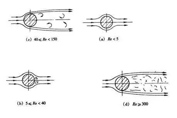
The Reynolds number Re of incompressible fluids is generally very large. In such cases, the boundary layer cannot encircle the backside of the cylinder but instead detaches from both sides of the cylinder surface, forming two shear layers that extend towards the tail during the flow. These two shear layers form the boundary of the wake, because the inner layer of the regulating valve moves much more slowly relative to the outer layer. Thus, these free shear layers tend to coalesce into discontinuous swirling vortices, resulting in a vortex flow in the wake. The vortex flow interacts with the cylinder, inducing vibration. When the vortices alternately detach from both sides of the cylinder, it also triggers periodic pulsating forces on the cylinder. This force causes the elastic cylinder to vibrate and produce a wind-like tone. When the wind blows over the wires, the wind noise can be heard, which is the phenomenon of vortex detachment. When the frequency of vortex detachment is close to or the same as the cylinder's natural frequency, the vibration increases, resonance occurs, and the noise increases. When Re > 3×10^5, the detachment of the vortices is very chaotic, and a wide frequency band is formed.
If the part has a non-circular cross-section, the above phenomenon and conclusion will also apply.
In summary, when compressible fluids flow through pneumatic control valves, at the smallest throttling section, they may reach or exceed the sound speed, thereby forming chaotic fluid flows such as shock waves, jet streams, and vortex flows. This chaotic fluid then converts into thermal energy downstream of the throttling orifice and generates gas dynamic noise. It spreads along the downstream pipeline and reaches various locations. In severe cases, excessive vibration may cause damage to the pipeline system.
Gas dynamic noise is generated when gas or steam flows through a throttling hole. The noise encountered in industrial applications of regulating valves is mostly gas dynamic noise. Gas and steam are both compressible fluids. Generally speaking, the flow velocity of compressible fluids is always higher than that of incompressible fluids. When the gas flow velocity is lower than the speed of sound, the noise is caused by intense turbulence; when the gas velocity is greater than the speed of sound, shock waves are generated in the fluid, resulting in a significant increase in noise. By comparing various noises, the noise produced by the flow of various compressible fluids through regulating valves is the most severe.
2. Liquid-powered noise
Liquid dynamic noise is generated when the liquid flows through the throttling orifice of the regulating valve. The structure of the regulating valve is diverse. The typical throttling forms are shown in the figure. Although the structural forms of various throttling orifices are different, they all have a throttling effect on the liquid. When the liquid passes through the throttling orifice, due to the sudden change in the area of the throttling orifice, the flow area decreases, the flow velocity increases, and the pressure drops. Therefore, it is prone to cause blocked flow, flash vaporization and cavitation effects, all of which are causes of noise.
When the pressure difference between the front and back of the valve throttling port is not significant, the noise at the throttling port is extremely low and the flow sound is not loud. Therefore, there is no need to consider the issue of noise. If the pressure difference is large, the fluid flowing through the regulating valve begins to undergo flash evaporation. The flowing fluid becomes a mixture of gas and liquid with bubbles, and the deceleration and expansion of the two-phase fluid naturally generate noise. Moreover, due to the sudden change in the cross-sectional area of the throttling section near the electric regulating valve port, the flow velocity becomes uneven under the high-speed jet state, thereby causing a kind of vortex detachment sound.
When cavitation occurs, the bubbles burst, and the powerful energy not only causes destructive force but also generates noise. The frequency of this noise can sometimes reach up to 10,000 Hz. The more and larger the bubbles, the more severe the noise will be.
When selecting a regulating valve, to avoid generating liquid dynamic noise, the key lies in finding the valve pressure drop ΔPc at which cavitation begins, and ensuring that the valve pressure drop is less than ΔPc. To achieve this, the concept of an initial cavitation coefficient KC is introduced.
The value of KC is obtained through experiments. It can also be determined based on the pressure coefficient of the liquid (FL). Figure 2 shows the relationship between FL and KC.
3. Vortex Detachment Noise
Among various types of noise, there is a kind of vortex-induced noise. Compressible fluids are prone to generating this kind of noise when flowing over the surface of an object. When fluid particles reach the leading edge of a non-streamlined cylinder, the flow is obstructed and the pressure rises from the pressure during free flow to another pressure, which is due to the conversion of fluid kinetic energy. After the fluid flows around the cylinder and forms a boundary layer, it continues to flow. The flow conditions of the regulating valve fluid vary at different Reynolds numbers (Re).
As can be seen from Figure 3, when Re < 5, the fluid does not detach from the cylindrical body (Figure a); when 5 ≤ Re < 40, a pair of stable vortices form closely behind the cylindrical body in the wake flow (Figure b); when 40 ≤ Re < 150, the symmetrical vortices break up, and stable, asymmetric, regularly arranged, and oppositely rotating vortices columns appear in the wake flow, and these vortices periodically detach from the cylindrical body (c); when Re > 150, the vortices column is no longer stable; when Re ≥ 300, the entire wake flow area has turned into a turbulent state (d).
The Reynolds number Re of incompressible fluids is generally very large. In such cases, the boundary layer cannot encircle the backside of the cylinder but instead detaches from both sides of the cylinder surface, forming two shear layers that extend towards the tail during the flow. These two shear layers form the boundary of the wake, because the inner layer of the regulating valve moves much more slowly relative to the outer layer. Thus, these free shear layers tend to coalesce into discontinuous swirling vortices, resulting in a vortex flow in the wake. The vortex flow interacts with the cylinder, inducing vibration. When the vortices alternately detach from both sides of the cylinder, it also triggers periodic pulsating forces on the cylinder. This force causes the elastic cylinder to vibrate and produce a wind-like tone. When the wind blows over the wires, the wind noise can be heard, which is the phenomenon of vortex detachment. When the frequency of vortex detachment is close to or the same as the cylinder's natural frequency, the vibration increases, resonance occurs, and the noise increases. When Re > 3×10^5, the detachment of the vortices is very chaotic, and a wide frequency band is formed.
If the part has a non-circular cross-section, the above phenomenon and conclusion will also apply.
In summary, when compressible fluids flow through pneumatic control valves, at the smallest throttling section, they may reach or exceed the sound speed, thereby forming chaotic fluid flows such as shock waves, jet streams, and vortex flows. This chaotic fluid then converts into thermal energy downstream of the throttling orifice and generates gas dynamic noise. It spreads along the downstream pipeline and reaches various locations. In severe cases, excessive vibration may cause damage to the pipeline system.